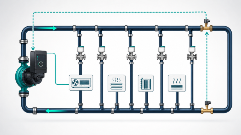

Open vs Closed Pump Systems: The Static Head Mistake That Oversizes HVAC Pumps
A plant room is at ground level and the top floor is 45 m higher. It is tempting to specify a circulation pump with at least 45 m head before adding pipe friction.
In a properly filled closed hydronic loop, the descending water column balances the ascending column. The pump does not continuously lift the same water from the plant room to the roof and leave it there. It circulates water around a closed path and mainly overcomes friction and equipment losses.
The 45 m elevation still matters. It affects fill pressure, expansion-vessel design, air management and component pressure rating. It does not normally become 45 m of pump differential head.
Define the system boundary before calculating head
The Hydraulic Institute describes total system head as the combination of:
- Static head from elevation and pressure differences between the system boundaries
- Friction loss in straight pipe
- Minor losses through fittings, valves and equipment
Choosing the wrong boundaries creates the wrong static-head term.
For an open transfer system, the boundaries may be the free surface of a lower tank and the free surface of an upper tank. The difference in surface elevation remains even at zero flow.
For a closed circulation loop, start and finish at the same point after travelling around the complete circuit. The net elevation change is zero. At zero flow, the pump normally needs no differential head to hold the filled loop stationary.
A worked comparison at the same design flow
Consider two systems designed for 100 m³/h.
The pipework and equipment create 12 m of friction loss at design flow. Assume turbulent water flow so the loss varies approximately with the square of flow.
Open transfer system
- Static elevation and pressure difference: 25 m
- Friction loss at 100 m³/h: 12 m
- Total design head: 37 m
Closed circulation system
- Net static head around the circuit: 0 m
- Friction loss at 100 m³/h: 12 m
- Total design head: 12 m
At 50% design flow, the approximate friction loss is:
12 × 0.5² = 3 m
The open system then requires:
25 + 3 = 28 m
The closed system requires:
0 + 3 = 3 m
| Flow | Open-system head | Closed-loop head |
|---|---|---|
| 0 m³/h | 25.0 m | 0.0 m |
| 25 m³/h | 25.8 m | 0.8 m |
| 50 m³/h | 28.0 m | 3.0 m |
| 75 m³/h | 31.8 m | 6.8 m |
| 100 m³/h | 37.0 m | 12.0 m |
The open-system curve starts at 25 m. The closed-loop curve starts at the origin.
Why the closed loop still needs pressure
Static fill pressure and pump differential pressure do different jobs.
The fill system and expansion vessel establish enough absolute pressure at the highest point to prevent air entry, boiling and loss of circulation. As water heats and expands, the vessel limits the pressure rise. Every component must remain within its minimum and maximum working pressure.
The circulation pump creates a differential pressure. It raises pressure on its discharge side and lowers it on its suction side relative to the no-flow distribution. Around the complete loop, that differential is consumed by pipe, fittings, coils, heat exchangers and control valves.
A designer can correctly select a 12 m differential-head pump for a loop whose bottom static pressure is several bar. Pump head and system pressure rating should appear as separate lines on the equipment schedule.
Equipment losses belong at their actual flow
The 12 m example should not be divided evenly across components without data. A real circuit might contain:
- Straight supply and return pipe
- Elbows, tees and reducers
- Isolation and balancing valves
- Control valve
- Strainer
- Chiller or boiler heat exchanger
- Terminal coils
- Flow meter
Use manufacturer pressure-drop data for coils, plate heat exchangers, strainers and control valves. For branches, calculate the index circuit—the route with the greatest required differential pressure at its design flow.
Do not add the pressure loss of parallel branches together. Each branch sees the differential between the common supply and return headers; their flows add, but their head losses do not stack in series.
When a “closed” system does have a static component
The zero-static-head rule applies to a completely filled closed loop with the same start and end boundary.
Additional head may be needed when:
- The system discharges through an open outlet
- A break tank separates parts of the circuit
- A make-up or transfer pump moves water between pressure zones
- The pump must maintain a defined pressure difference between two vessels
- Part of the route can drain or contain air
- A process consumes water instead of returning it
A district-energy network can contain closed circulating sections and open make-up or transfer duties. Calculate each pump from its own boundaries.
Control implications are different
In a friction-dominated closed loop, reducing flow sharply reduces required head. This makes variable-speed control particularly effective when the sensor and setpoint allow differential pressure to fall with demand.
In an open system dominated by 25 m static head, the drive cannot reduce head below the static requirement. The minimum useful speed is therefore higher, and ideal cube-law energy estimates can overstate savings.
Plot a family of system curves for:
- Clean and dirty strainers
- Different control-valve positions
- Minimum and maximum tank levels
- Branches entering and leaving service
- Normal and emergency operating modes
Then overlay the pump curves at each intended speed.
A clearer design schedule
Instead of one ambiguous line marked “pump head,” record:
- Static head between defined boundaries
- Pipe friction at design flow
- Equipment and valve losses
- Design contingency, stated once
- Required pump differential head
- Minimum fill pressure at the pump
- Maximum system working pressure
- Highest-point minimum absolute pressure
For building circulation duties, compare SHXINHUO’s HVAC pump range, ISG inline pumps and GPD circulators only after the index circuit and control method are defined.
Building height is not irrelevant. It is simply assigned to the pressure-maintenance calculation instead of being charged to the circulation pump a second time.
Technical references
- Hydraulic Institute Data Tool — System Curves
- Hydraulic Institute Data Tool — Combined Pump and System Curves
- U.S. Department of Energy — Variable Speed Pumping: A Guide to Successful Applications
Data note
The 25 m static head and 12 m design friction are illustrative. Actual closed-loop head must be calculated from the index circuit, current equipment data and the selected control-valve authority.