
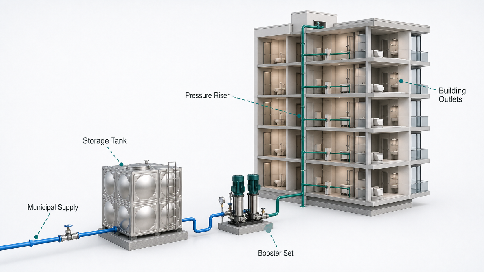
How to Size a Booster Pump System for a Multi-Storey Building
Water pressure complaints in a tall building usually appear at the extremes: weak flow on the upper floors and excessive pressure on the lower floors. Choosing a larger pump may solve the first problem while making the second one worse.
A booster system has to do two things at once. It must supply enough flow during peak demand, and it must maintain acceptable pressure as demand changes throughout the day. Building height is only one part of the calculation.
Start with the available inlet condition
Measure or obtain the water-main pressure at the proposed connection point. A single daytime reading is not enough. Municipal pressure can vary by time, network demand and local operating conditions.
For conservative sizing, use the lowest credible inlet pressure unless a break tank creates a known suction condition. Also confirm whether direct boosting from the public main is permitted by local regulations. Some authorities require an atmospheric storage tank or break tank to protect the network from negative pressure and contamination risk.
The inlet data should include:
- Minimum, normal and maximum supply pressure
- Elevation of the connection and pump room
- Available pipe size and meter loss
- Storage-tank level range, if used
- Water temperature and quality
Estimate probable peak flow
The booster should not be sized by adding the maximum flow of every tap, shower and appliance. Buildings rarely use all fixtures at once. Plumbing design methods apply diversity or probability to estimate the likely simultaneous demand.
Use the method required by the local plumbing code or project standard. Building type matters: an apartment tower, hotel, hospital, school and office can have very different demand patterns even when the fixture count is similar.
Record more than the peak. A booster system operates for many hours at low or moderate demand, so the load profile is important for pump staging and control. Night-time flow can be a small fraction of morning or evening peaks.
Calculate the required discharge pressure
At the design flow, the pump must provide enough pressure to overcome:
- Vertical elevation from the pump to the highest outlet in the pressure zone
- Friction loss in pipe and fittings
- Pressure loss through meters, filters, backflow preventers, valves and equipment
- Required residual pressure at the most remote fixture
- A clearly stated design margin
In water terms, one bar is approximately 10.2 metres of head. This is useful for a quick sense check, but the final calculation should use consistent units and actual component data.
If a pump draws from a pressurised main, the minimum inlet pressure reduces the required pump differential pressure. If it draws from a break tank, the liquid level relative to the pump suction affects the suction head.
Why tall buildings are divided into pressure zones
Suppose a basement booster is selected to deliver sufficient pressure at the top floor of a very tall building. That same discharge pressure acts on the lower floors unless pressure-reducing valves absorb it. The system pays to create pressure and then pays again to remove it.
Pressure zoning divides the building into manageable sections. Grundfos guidance describes zoning as a way to prevent large pressure variation between floors, with typical guidance of maintaining about 1.5–2 bar minimum at the top of a zone and avoiding more than roughly 4–4.5 bar at its lowest floor. Local codes and fixture ratings always take priority, but these values are a useful early-design reference.
Common layouts include:
- Basement booster sets serving separate zones: straightforward operation and centralised maintenance, but high-pressure risers may be required.
- Cascade boosting: a lower booster supplies an intermediate zone or break tank, and another booster serves the next zone.
- Roof tank with gravity distribution: provides storage and can offer resilience, but adds structural load and water-quality considerations.
- Single high-pressure booster with pressure-reducing valves: simple in concept, but can waste energy and expose lower piping to higher pressure.
The right arrangement depends on height, floor layout, plant-room availability, local rules, required resilience and life-cycle cost.
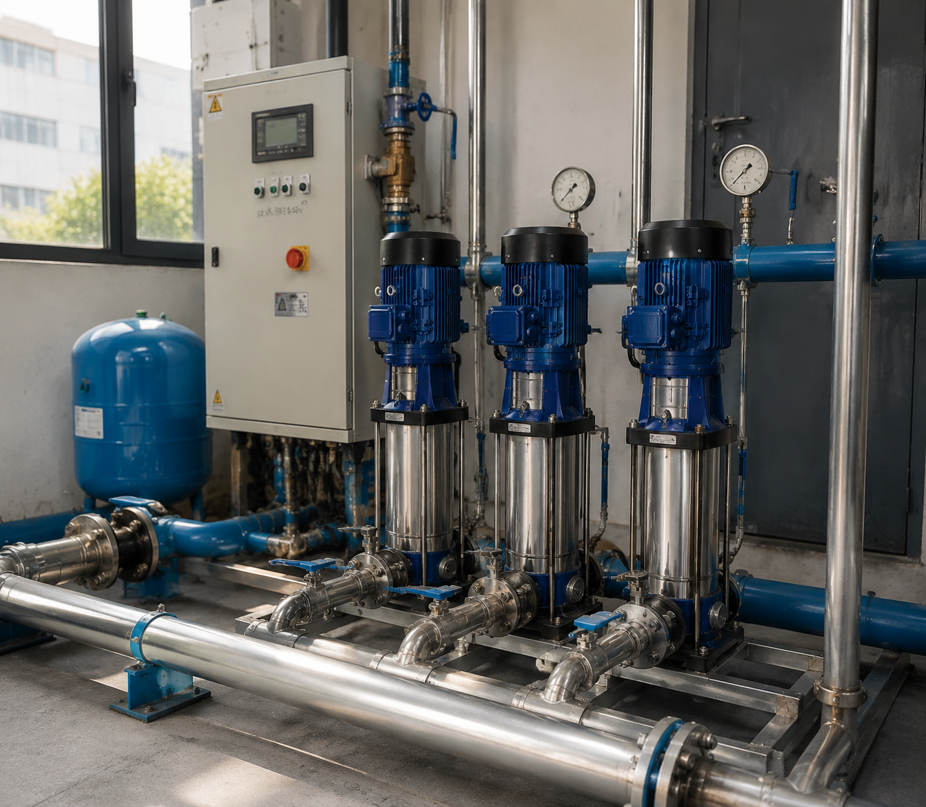
Select the number and size of pumps
A single pump sized for peak demand may cycle or operate inefficiently during low-flow periods. Multiple pumps can follow demand more closely and provide redundancy.
A common arrangement is two or three pumps with variable-speed control. The lead pump handles low and moderate demand. Additional pumps stage on as flow increases. The controller rotates lead duty to balance running hours.
When comparing arrangements, check the combined pump curves. Pumps in parallel increase available flow, but the actual gain depends on the system curve. Two pumps in parallel do not automatically deliver twice the single-pump flow.
For applications where supply interruption has serious consequences, define redundancy explicitly—for example, whether the remaining pumps must meet 100% of design demand with one pump out of service.
Use variable speed for pressure stability
Demand in a building changes quickly. A VFD-controlled booster adjusts pump speed to maintain a pressure setpoint as outlets open and close. This improves comfort and reduces the need to dissipate excess pressure across valves.
Good control still requires commissioning. Setpoints should be high enough for the critical outlet, not simply as high as the pump can deliver. Remote pressure sensing or setpoint compensation may reduce unnecessary pressure at low flow, especially in long distribution systems.
Also review:
- Minimum pump speed and stable operating region
- Small pressure tank or other method to reduce short cycling
- No-flow shutdown
- Dry-run and low-inlet-pressure protection
- Check-valve operation
- Staging and de-staging delays
- Alarm communication to the building-management system
Check suction and tank design
A high-head multistage pump still needs good suction conditions. Keep the suction line short and generously sized, limit fittings and avoid high points that trap air. Confirm NPSHA at the lowest tank level and highest water temperature.
Where a break tank is used, its volume should follow local code, refill capacity and the required storage duration. Too small a tank can cause unstable inlet conditions; too large a tank may create water-age and space problems.
Information to send with a booster enquiry
To obtain a useful proposal, provide:
- Building type and number of floors
- Elevation of each pressure zone
- Probable peak flow for each zone
- Required residual pressure at the critical fixture
- Minimum and maximum inlet pressure
- Pipe and equipment losses
- Tank level and suction arrangement
- Duty/standby requirement
- Electrical supply and control interface
- Material, potable-water and certification requirements
This allows the pump supplier to select a hydraulic arrangement rather than simply nominate a motor size.
Match the pump architecture to the pressure duty
Multistage centrifugal pumps are commonly used for building boosting because several impellers add head in a compact package. Vertical designs save floor space, while horizontal multistage pumps may suit smaller plant rooms or package arrangements.
SHXINHUO supplies clean-water pressure-boosting pumps for distributors, OEM customers and building projects. The current range includes the CDL vertical multistage centrifugal pump, MHI horizontal multistage booster pump and TD multistage inline pump. Project buyers can submit zone flow, differential head, inlet pressure, power supply and redundancy requirements for a preliminary selection review. A final booster set still has to be engineered around local plumbing rules and the complete building demand profile.