How to Choose a Multistage Booster Pump for a Building
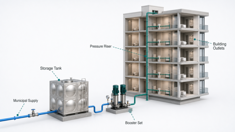
A building booster does not operate at one flow all day. Morning peak, night demand, fire provisions, tank filling and the incoming main all change the duty.
Understanding how to choose a multistage booster pump means defining that demand range before selecting the number of stages or the motor size.
Begin with the pressure boundary
Choose the inlet point and the most demanding outlet. Record:
- Minimum reliable inlet pressure at design flow
- Elevation from the inlet gauge to the critical fixture or tank
- Required residual pressure at that outlet
- Loss through pipe, fittings, meters, backflow devices and valves
- Any pressure required by downstream equipment
Do not use the best daytime pressure shown on a utility bill. The pump must work with the minimum credible source pressure when building demand is high.
A worked high-rise example
Consider this illustrative booster pump sizing case:
- Peak domestic flow: 18 L/s
- Critical outlet: 65 m above the booster inlet
- Required residual pressure at the outlet: 250 kPa
- Pipe and fitting loss at peak flow: 120 kPa
- Meter and backflow-device loss: 50 kPa
- Minimum inlet pressure at peak flow: 150 kPa
The net pressure rise required is:
Elevation pressure + outlet pressure + losses − inlet pressure
Using 9.81 kPa per metre of water:
(65 × 9.81) + 250 + 120 + 50 − 150 = 907.7 kPa
This is approximately:
907.7 ÷ 9.81 = 92.5 m of water head
The preliminary peak duty is therefore 18 L/s at about 92.5 m. It still needs a demand profile, zoning check and current product curve before a pump is selected.
Check whether one pressure zone is sensible
A high pressure water booster pump serving the top floor can expose lower floors to excessive static pressure when demand falls. Pressure-reducing valves can manage part of that difference, but very tall buildings may benefit from separate zones or intermediate booster locations.
Zoning affects:
- Maximum pressure on lower-level pipework and fixtures
- Required pump head and stage count
- Pressure-reducing valve duty
- Tank location and usable storage
- Resilience if one zone is isolated
The Hydraulic Institute notes that variable-speed pressure booster systems may be located at multiple elevations in high-rise buildings. The correct arrangement depends on local plumbing rules and the building pressure limit, not on height alone.
Select for the demand profile, not only peak flow
An apartment or hotel may spend many hours far below design flow. One large fixed-speed pump sized for the peak can operate inefficiently or cycle at night.
A staged set of smaller pumps can cover a wider range. One unit handles low demand; additional pumps start as flow rises. Variable speed can maintain discharge pressure while reducing unnecessary head, provided the control sensor and setpoint represent the actual system need.
The sequence should be checked against composite pump curves. Two identical pumps in parallel do not automatically deliver twice the flow because the operating point moves along the system curve.
Decide what redundancy means
For a building water supply booster pump, specify the required capacity with the largest unit unavailable. “N+1” is meaningful only after the duty is defined.
Examples include:
- Three pumps, each sized for 50% of peak, so two meet design flow
- Three pumps with one lead, one assist and one standby
- Two pumps, each capable of the full domestic peak
The best arrangement depends on peak duration, acceptable loss of service, plant space and maintenance access. Equal run-time rotation can spread wear, but it does not remove the need to test standby operation.
Check the entire curve and motor
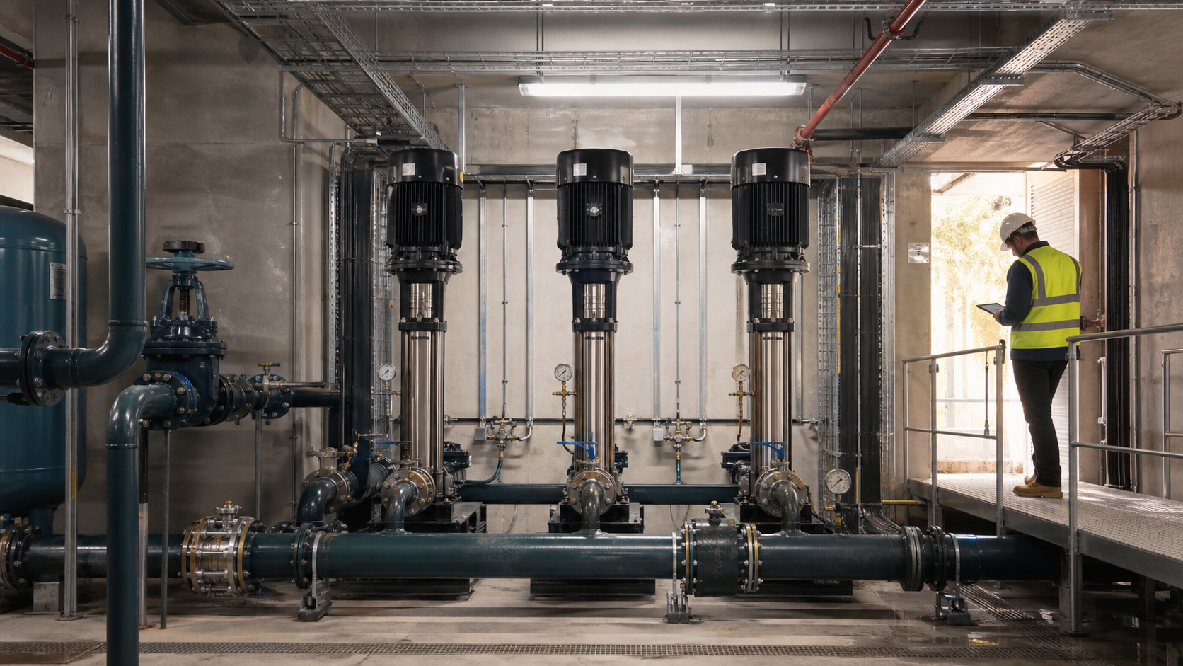
A vertical multistage pump develops head through several impeller stages. Stage count helps reach the duty, but the motor must cover the highest absorbed power at every permitted operating point.
Review:
- Minimum, normal and maximum flow
- Pump efficiency and best-efficiency region
- NPSH required at maximum flow
- Absorbed power at minimum inlet pressure and every allowed speed
- Maximum working pressure of pump, manifold and fittings
- Seal and material compatibility with the water
- Maximum starts and VFD operating limits
At high inlet pressure, pump casing pressure can be greater even though required boost head is lower. Check maximum allowable working pressure against the sum of inlet pressure and pump shutoff pressure.
Pressure control needs a real sensor strategy
A sensor at the pump discharge sees plant-room pressure, not pressure at the critical outlet. If pipe loss changes sharply with flow, holding one high discharge setpoint wastes energy during light demand.
Options include remote sensing, setpoint reset based on flow, or a calculated pressure-loss compensation curve. The control must also prevent rapid staging, hunting and operation below the manufacturer’s minimum flow.
Provide a small pressure vessel where required to manage leakage demand and reduce starts. Size it from system and control requirements rather than using it as a cure for unstable programming.
Use measured data where a system already exists
For a replacement, log inlet pressure, discharge pressure, flow and electrical input across representative days. The U.S. Department of Energy documented a booster retrofit in which replacing a mismatched single-pump arrangement with three smaller adjustable-speed pumps reduced annual electricity use from 280,400 kWh to 55,300 kWh. That 80% result belonged to one measured system; it is evidence for measurement and right-sizing, not a universal savings claim.
SHXINHUO’s CDL vertical multistage pumps, MHI horizontal multistage pumps and TD multistage pipeline pumps suit different layouts and duty ranges. A final multistage pump selection needs the pressure-zone diagram, demand range and required redundancy.
What to include in an enquiry
Send peak and minimum flow, hourly demand if available, inlet-pressure range, critical elevation, outlet-pressure target, calculated losses, maximum system pressure, required redundancy, power supply, materials and installation constraints.
That information allows the supplier to compare pump quantity, stage count and control strategy without hiding assumptions inside a safety margin.
Technical references
- Hydraulic Institute — Pumping Systems in Commercial Building Services
- Hydraulic Institute — Five Keys to Understanding Parallel Pump Optimization
- U.S. Department of Energy — New Water Booster Pump System Reduces Energy Consumption by 80 Percent
- Hydraulic Institute Data Tool — Combined Pump and System Curves
Data note
The 18 L/s example is illustrative. Building water design, residual pressure, zoning, diversity, storage, hygiene, fire separation and pressure limits must follow the applicable local codes and the current data for the exact booster equipment.