Variable-Speed Pumping in HVAC: Why Control Strategy Matters More Than Motor Speed
Variable-speed drives are now common in chilled-water and heating-water systems. Yet two buildings with similar pumps and similar drives can show very different energy performance.
The difference is often not the drive itself. It is the way the pump is controlled.
A VFD can reduce pump speed, but it needs a sensible signal and a realistic setpoint. If the differential-pressure target is too high, the sensor is poorly located or minimum flow is misunderstood, the system may use far more energy than expected.
Why speed reduction can produce large savings
For the same centrifugal pump and impeller, the affinity laws describe the approximate relationship between speed and performance:
- Flow changes in proportion to speed.
- Head changes approximately with the square of speed.
- Power changes approximately with the cube of speed.
As a simple illustration, reducing speed to 80% gives an idealised power ratio of 0.8³, or about 51%. Real input power will differ because pump, motor and drive efficiency change with load, but the relationship explains why speed control can be so effective in variable-flow systems.
There is an important limitation. These savings are strongest where friction loss dominates, as in many closed hydronic distribution loops. Systems with a large static-head component do not follow the same simple pattern. The U.S. Department of Energy’s variable-speed guide specifically warns that the system curve must be considered before applying affinity-law savings.
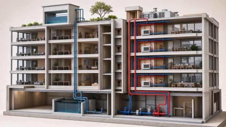
The typical variable-flow HVAC loop
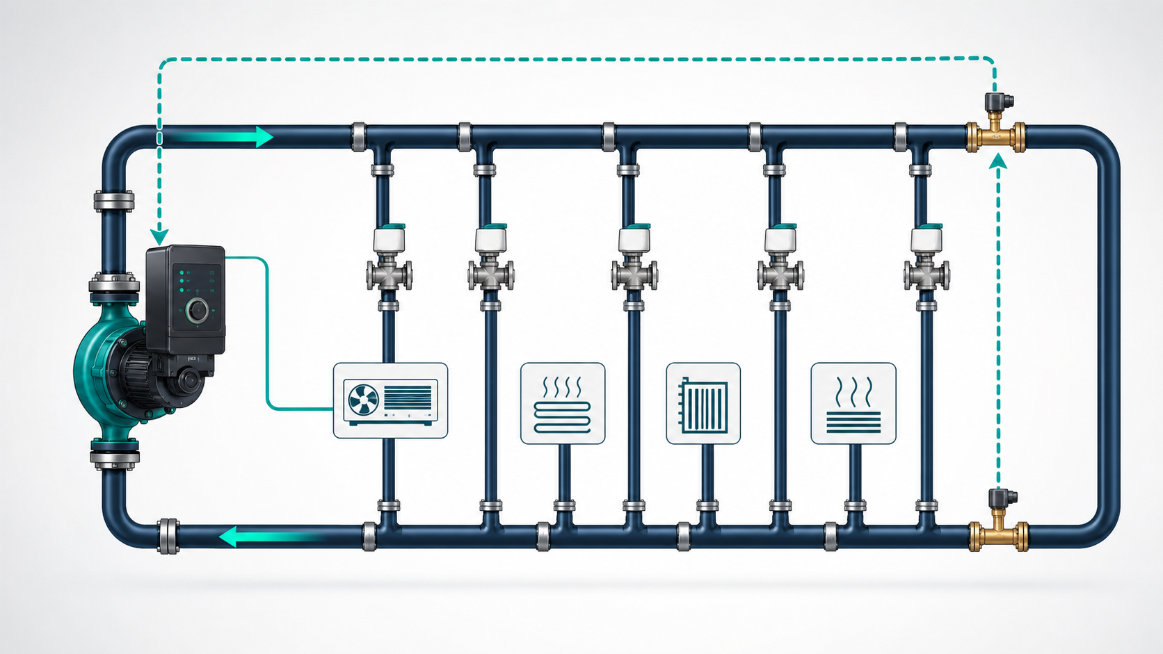
In a system with two-way control valves, terminal-unit valves close as heating or cooling demand falls. Flow decreases and system resistance rises. If a fixed-speed pump continues at full output, differential pressure increases. Valves may become noisy and the pump wastes energy against unnecessary resistance.
A VFD allows the pump to slow down as demand falls. A differential-pressure sensor sends feedback to the controller, which adjusts speed to maintain the required pressure for the active branches.
This sounds straightforward, but three decisions determine whether it works well.
Decision 1: Where should differential pressure be measured?
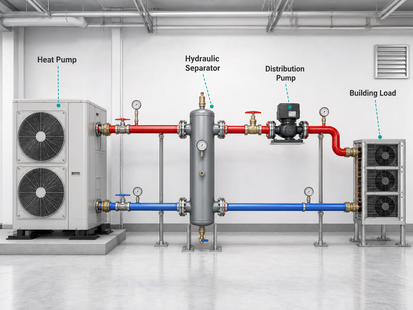
If the sensor is installed directly across the pump, the controller maintains pump differential pressure rather than proving that the remote system has enough pressure. The setpoint often has to remain high enough for the worst-case circuit, even when only nearby circuits need water.
A remote sensor near the hydraulically critical circuit can allow the pump setpoint to represent actual distribution demand more accurately. The best location depends on system layout and control architecture; long networks or changing critical circuits may require multiple sensors or a different reset strategy.
ASHRAE guidance also describes using control-valve position as a supervisory signal. The aim is to operate with at least one representative valve nearly open, rather than forcing many valves to throttle excess pressure.
Decision 2: Should the pressure setpoint be constant?
A constant differential-pressure setpoint is simple and can be appropriate when the pressure requirement remains nearly unchanged as flow varies. However, pipe friction falls rapidly at lower flow. Holding design pressure at part load can therefore be unnecessary.
Proportional-pressure control reduces the pressure target as flow falls. This is well suited to many circulating HVAC systems with two-way valves. Quadratic pressure reset can follow the theoretical friction curve more closely, although commissioning must confirm that remote coils still receive adequate flow.
The right curve is not universal. Underfloor heating, small constant-pressure branches, minimum-flow circuits and systems with dominant equipment pressure drops may require a different strategy.
Decision 3: What is the safe minimum speed?
“Slower” is not always “better.” Minimum speed must protect the complete system, not just the pump.
Check:
- Minimum flow through chillers, boilers and heat exchangers
- Flow-switch and differential-pressure requirements
- Risk of air accumulation at low velocity
- Control-valve authority and sensor accuracy
- Pump operating region and motor cooling
- Potential mechanical resonance at particular speeds
- Freeze protection and water-quality requirements
The DOE recommends programming drives to avoid speeds that create equipment or system resonance. A minimum speed should be established during commissioning using measured flow and equipment limits, not chosen as an arbitrary percentage.
Constant flow, constant pressure or proportional pressure?
The control mode should follow the hydraulic behaviour of the application.
Constant speed or constant curve may suit a genuinely constant-flow circuit.
Constant differential pressure may suit variable flow where the required pressure is largely independent of flow, or where a specific pressure must be maintained across a component.
Proportional differential pressure is often effective in two-way-valve heating and cooling networks because pipe friction reduces as flow falls.
Temperature-based control can work in selected domestic hot-water return or process heat-transfer applications, but it must be designed around hygiene, comfort and minimum circulation requirements.
Common reasons VFD projects underperform
- The pump is still oversized. A drive can move the operating point, but a severely oversized pump may spend its life at an inefficient low speed or outside a stable operating region.
- The setpoint was copied from design documents and never commissioned. Conservative design pressure becomes a permanent operating target.
- The sensor is located for convenience. The control signal does not represent the critical circuit.
- A bypass remains open. Water circulates without serving useful load.
- Balancing and control valves fight the pump. Excess pressure is created and then removed.
- Parallel pumps are poorly staged. Multiple pumps run at inefficient low load when fewer pumps at a better duty would use less power.
- No trend data is reviewed. Speed, differential pressure and valve position are not used to improve the sequence.
A commissioning sequence that produces useful results
Start with the design flow and verify that the pump, valves and terminal units can deliver it. Confirm sensor calibration and direction. Then reduce the differential-pressure setpoint gradually while monitoring the critical circuits.
Trend at least:
- Pump speed and power
- Supply and return pressure
- Differential-pressure setpoint
- Representative valve positions
- Loop flow, where available
- Supply and return temperature
- Equipment alarms and minimum-flow status
The objective is not the lowest possible pressure. It is the lowest pressure that reliably meets the load under all intended operating conditions.
Choose the pump and control as one package
A good HVAC selection combines the hydraulic curve, expected load profile, motor efficiency, control mode and system instrumentation. Small circulators can benefit from permanent-magnet motors and integrated variable-frequency control, while larger loops may use inline pumps with external drives and building-management-system integration.
SHXINHUO’s HVAC pump range covers compact hydronic circulation, domestic hot-water return and larger building-service loops. Relevant starting points include the AHBP permanent-magnet variable-frequency circulation pump, GPD inline circulation pump and ISG inline HVAC centrifugal pump. For OEM customers and project buyers, control mode, voltage, connection size and operating curve can be reviewed together rather than treating the pump and controller as separate items. The final sequence must still be commissioned against the actual piping and equipment limits.