How to Size a Centrifugal Pump Without Oversizing It
An oversized pump can look like a safe choice. It gives the project a margin, appears to protect against future demand and reduces the risk of selecting a model that is too small. In practice, that extra capacity often has to be removed again with a throttling valve, a bypass or excessive system resistance.
The result is not additional reliability. It is usually higher energy use, more noise and a pump that spends its working life away from its intended operating region.
A better selection starts with one question: what flow and head does the system actually require?
1. Define the required flow rate
Flow is determined by the job the system must perform. It should not be copied from the existing pump nameplate without checking whether the original pump was correctly selected.
For a transfer system, flow may come from the volume that must be moved within a given time:
Flow = required volume ÷ available transfer time
For a heating or cooling loop, the design flow comes from the thermal load and the selected temperature difference. For a building water-supply system, it comes from the probable simultaneous demand rather than the sum of every fixture at full flow. Wastewater applications may also need a minimum velocity in the discharge pipe to keep solids moving.
Before selecting a pump, record both the normal flow and the realistic minimum and maximum. A single design number is not enough for a system with changing demand.
2. Calculate total dynamic head—not just building height
Total dynamic head is the resistance the pump must overcome at the required flow. It has two main parts:
- Static head: the vertical pressure difference between the suction and discharge conditions.
- Friction head: the loss through pipe, fittings, valves, strainers, heat exchangers and other equipment.
The common mistake is to use only the vertical height. That can understate the duty in a long or restrictive piping system. The opposite mistake is to add several unrelated safety factors to the static head, pipe loss and equipment loss. That produces an inflated duty point and an oversized pump.
Use the actual pipe material, internal diameter, length and fitting count. Check equipment pressure drops at the design flow. In a closed HVAC loop, the pump generally does not “lift” the water to the top of the building on every circuit; the static elevation is balanced by the return side. The pump mainly overcomes dynamic losses in the closed loop.
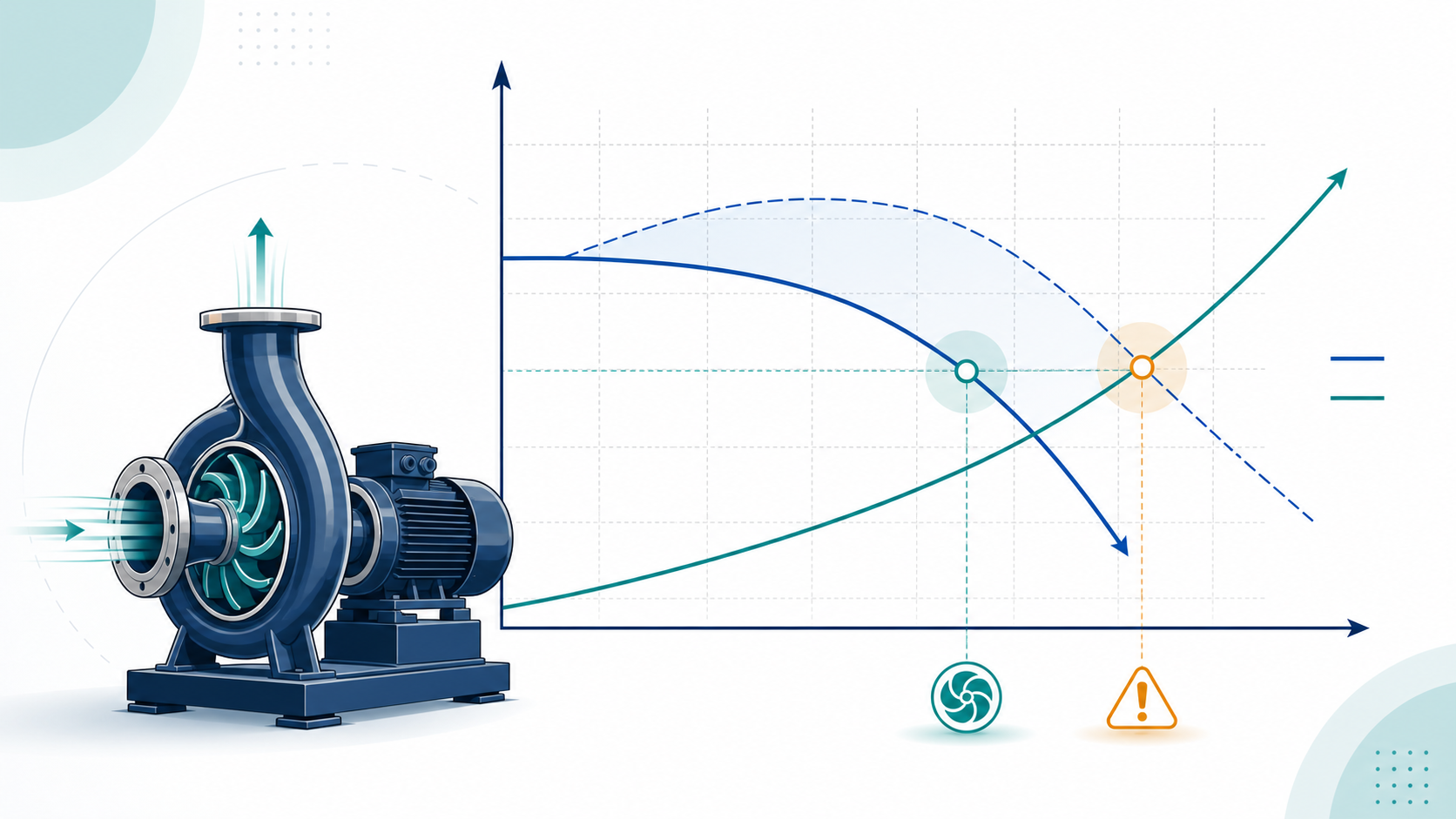
3. Draw the system curve
Friction loss changes approximately with the square of flow. If flow doubles, the friction component of head rises by roughly four times. Plotting this relationship creates the system curve.
The operating point is where the system curve intersects the pump curve. This matters because a centrifugal pump does not deliver one fixed flow. Its actual flow is established by the interaction between the pump and the system.
If the system is modified—perhaps a valve closes, a filter becomes dirty or another branch opens—the system curve changes and the operating point moves.
4. Select near the best efficiency point
The best efficiency point, or BEP, is the point on a pump curve where hydraulic efficiency is highest. It is also a useful reference for mechanical reliability. Operation far to the left or right of BEP can increase recirculation, radial loading, vibration and seal or bearing stress.
The U.S. Department of Energy advises selecting a centrifugal pump so the system curve intersects the pump curve close to BEP; its selection tip sheet uses a range within 20% of BEP as a practical screening target. The final acceptable operating region should still follow the manufacturer’s curve and the applicable Hydraulic Institute guidance.
Do not compare efficiency only at the design point. If demand varies, check the expected operating points across the load profile. A pump with a broad, stable efficiency range can be a better choice than one with a slightly higher peak efficiency but poor part-load performance.
5. Check power across the full curve
Motor selection should be based on the absorbed power shown on the pump curve, not simply on hydraulic output at one point. Check whether power rises toward runout and make sure the selected motor will not overload at any permitted operating condition.
Also confirm the electrical supply, starting method, ambient temperature and any service factor requirements. A larger motor does not correct a poor hydraulic selection; it only prevents the motor from tripping while the pump continues to operate inefficiently.
6. Verify suction conditions and NPSH margin
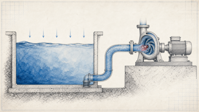
Net positive suction head available, NPSHA, is a system property. Net positive suction head required, NPSHR, is supplied by the pump manufacturer for a particular flow and speed.
NPSHA must exceed NPSHR by an appropriate margin. Simply matching the two values is not a robust design. Hydraulic Institute guidance explains that published NPSH3 is associated with a 3% head reduction during testing; an additional margin is needed for reliable service.
When checking suction conditions, include:
- Absolute pressure at the liquid surface
- Static suction head or lift
- Suction-pipe friction loss
- Liquid vapour pressure at the maximum operating temperature
- Restrictions at strainers, foot valves and fittings
- Site elevation, where atmospheric pressure is lower
Insufficient margin can lead to cavitation, reduced performance, noise and impeller damage.
7. Add margins once—and document them
Some margin is reasonable. Pipe roughness may increase, demand estimates have uncertainty and future changes may be planned. The problem is hidden, repeated margin.
For example, the consultant adds 10%, the contractor adds another 10%, and the buyer moves to the next larger model “to be safe.” These margins multiply. The final pump may be far from the original requirement.
State the margin clearly and apply it once. If future expansion is important, consider a pump with an adjustable impeller, variable-speed control or parallel staging instead of permanently operating one oversized pump at a restricted flow.
A practical selection checklist
Send the pump supplier the following information:
- Required, minimum and maximum flow
- Total dynamic head at the required flow
- Liquid type, temperature, density and viscosity
- Solids content or particle size, if present
- Suction arrangement and calculated NPSHA
- Operating hours and demand profile
- Pipe connection and installation limits
- Power supply, motor and control requirements
- Material and seal requirements
- Any redundancy or future expansion requirement
With this information, the supplier can compare the duty against the full curve rather than selecting from nominal pipe size or motor power.
The selection is a system decision
Pump efficiency cannot compensate for an incorrect duty point. Start with realistic flow, calculate total head, examine where the system curve meets the pump curve and confirm power and suction conditions.
SHXINHUO manufactures centrifugal pumps for HVAC, building water supply and wastewater applications, with OEM/ODM and project-supply support for distributors and contractors. For an initial clean-water selection, compare the ISG single-stage inline centrifugal pump, TD multistage pipeline pump and CDL vertical multistage centrifugal pump. SHXINHUO’s selection team can review a duty sheet, but the final model should always be confirmed against the actual system curve, motor load and suction conditions.