Wet-Well Sizing: Turning Pump Starts per Hour into a Working Volume
A small wet well keeps excavation cost down and reduces wastewater retention. Make it too small, however, and a constant-speed pump may start repeatedly during moderate inflow. Each start adds thermal and electrical stress.
A large wet well lengthens the cycle, but it can also hold wastewater long enough to encourage odour, septicity and solids deposition.
Working volume is therefore a balance. It must be checked alongside pump submergence, intake hydraulics, alarm storage, incoming-sewer levels and the manufacturer’s start limit.
Working volume is not total wet-well volume
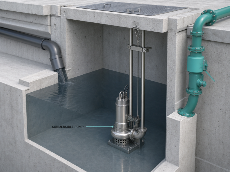
The working volume is the liquid volume between the normal pump-on and pump-off levels. It is the volume filled and emptied during a normal cycle.
The total structure also needs space for:
- Minimum pump submergence
- Clearance above the floor and intake
- Lag-pump start level
- High-level alarm
- Emergency storage before overflow
- Freeboard and access requirements
Do not use the calculated working volume as the excavation volume.
Why the worst cycling occurs near half pump rate
For one constant-speed pump:
- Qp is pump discharge rate
- Qin is steady inflow
- V is working volume
While the pump is off, filling time is:
tfill = V ÷ Qin
While the pump is on, the wet well empties at the net rate Qp − Qin:
tpump = V ÷ (Qp − Qin)
The total cycle time is shortest—and starts per hour are greatest—when inflow is approximately half the pump rate.
At Qin = Qp ÷ 2:
minimum cycle time = 4V ÷ Qp
Rearranging gives a useful preliminary equation:
V = Qp × T ÷ 4
Where T is the required minimum cycle time.
Worked example: a 40 L/s sewage pump
Assume:
- One duty pump with one standby pump
- Constant-speed pump rate: 40 L/s
- Required minimum cycle time: 10 minutes
- Circular wet well internal diameter: 3.0 m
Convert pump rate:
40 L/s = 2.4 m³/min
Working volume:
V = 2.4 × 10 ÷ 4 = 6.0 m³
The Ontario sewage-works guideline gives the same result for pumps of 50 kW or smaller in a two-pump constant-speed station: working volume in m³ equals 0.15 times one pump’s rate in L/s.
0.15 × 40 = 6.0 m³
This is a design example, not a universal code value. Local authority criteria and the pump manufacturer’s permitted starts take precedence.
Convert volume into a usable level band
For a 3.0 m diameter circular wet well:
Area = π × 3.0² ÷ 4 = 7.07 m²
The level difference between pump-on and pump-off is:
6.0 ÷ 7.07 = 0.85 m
Changing the target cycle time changes both working volume and level band:
| Minimum cycle time | Working volume | Level band in a 3.0 m well |
|---|---|---|
| 5 min | 3.0 m³ | 0.42 m |
| 10 min | 6.0 m³ | 0.85 m |
| 15 min | 9.0 m³ | 1.27 m |
| 20 min | 12.0 m³ | 1.70 m |
A longer cycle cannot simply be selected because it is kinder to the motor. The resulting level band may conflict with incoming-sewer elevation, minimum submergence or allowable storage time.
Confirm starts with the actual inflow range
The QpT/4 equation checks the theoretical worst steady inflow for one constant-speed pump. A real station has variable inflow, alternating duty, lag-pump staging and sometimes variable speed.
Build a cycle table using:
- Initial average flow
- Design average flow
- Peak instantaneous flow
- Infiltration and wet-weather cases
- One pump operating
- Lead and lag pumps operating
- Largest pump unavailable
For each case, confirm fill time, pump run time, starts per hour and high-level storage.
Alternating lead pumps shares starts between motors, but it does not remove the hydraulic cycle. A lag-pump start level also reduces the remaining emergency volume, so the control levels must be checked as a complete stack.
A small station must still pass the peak flow
Wet-well volume cannot compensate for inadequate firm pumping capacity. The station must meet the authority’s peak-flow requirement with the defined standby philosophy.
The Ontario guideline also calls for system-head calculations over different wet-well levels and pipe roughness conditions. Changing water level changes static head; ageing or fouling changes forcemain friction. Plot the pump curve against the resulting family of system curves.
Check the motor over the full range. At a high wet-well level, reduced static head can move the pump to higher flow and higher absorbed power.
Retention and solids set an upper limit
Holding wastewater longer can create odour and corrosion problems. Ontario guidance says effective volume should consider average daily flow with a filling time not exceeding 30 minutes unless flow equalisation is intended. The U.S. EPA has also warned that excessive wet-well detention can contribute to sulphide generation.
Good geometry helps:
- Slope the floor toward the pump intake
- Avoid dead pockets
- Prevent a falling inlet jet from driving air into the pump
- Maintain manufacturer-required submergence
- Avoid vortices and strong pre-swirl
- Provide safe access and ventilation
The wet well should be no larger than the hydraulic, cycling and emergency-storage calculations require.
Solids handling extends beyond the pump model
For raw sewage, the Ontario guideline specifies pumps capable of passing at least an 80 mm sphere, except where grinder pumps are used, and suction/discharge openings of at least 100 mm. It also calls for a minimum 0.6 m/s velocity in the forcemain at firm design capacity.
Those figures are jurisdiction-specific design guidance, not a worldwide specification. They illustrate why “40 L/s at 18 m” is not enough information for a wastewater pump enquiry.
Also state:
- Maximum solids size
- Rag and fibre content
- Free passage requirement
- Forcemain diameter and length
- Minimum cleansing velocity required by the authority
- Expected grit or abrasives
- Need for cutting, vortex or channel impeller
SHXINHUO’s sewage pump range, submersible pumps and cutting pumps serve different solids-handling conditions. The wet-well geometry and control levels remain part of the pump selection.
What the design drawing should show
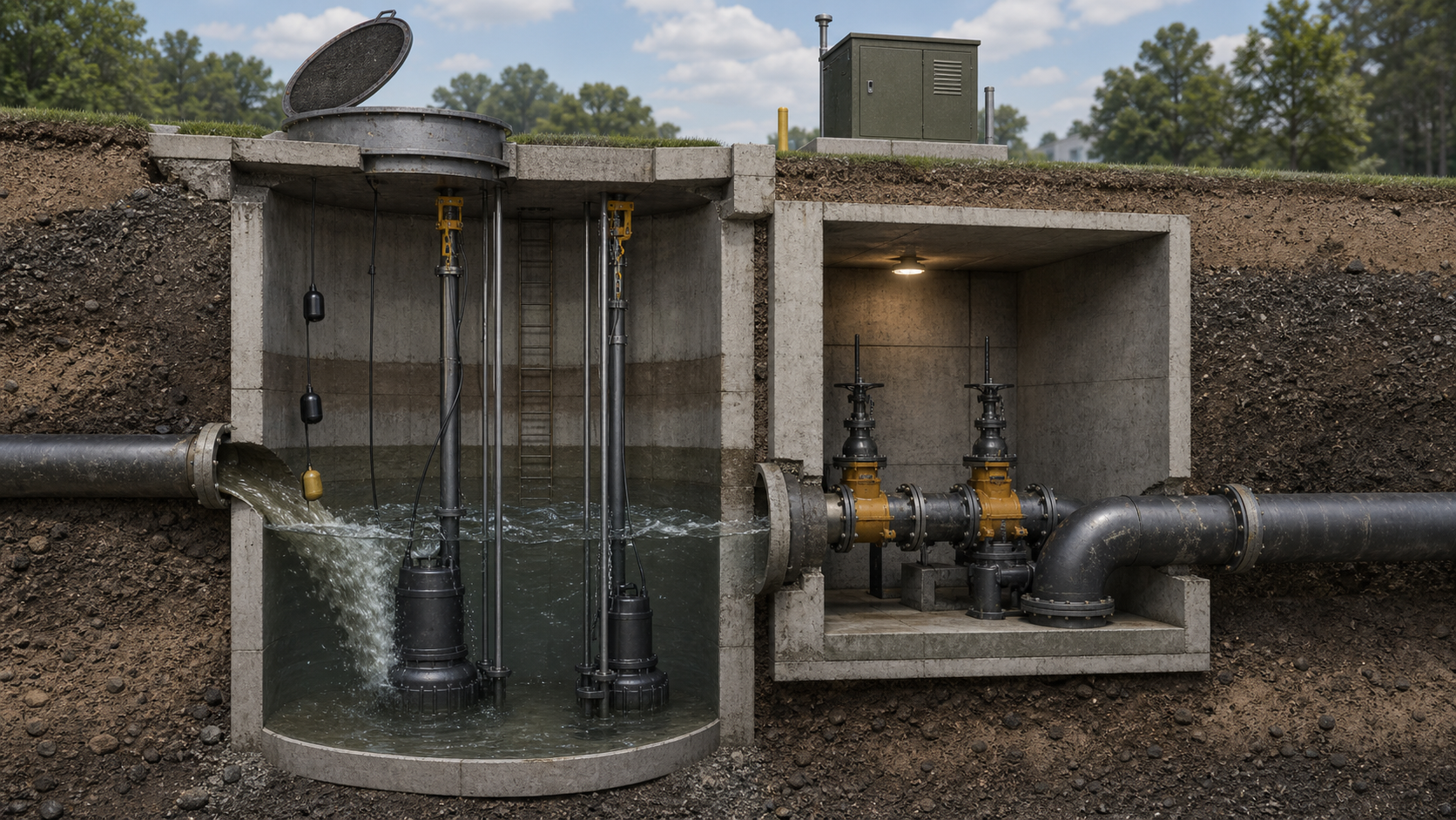
Record every level on one section:
- Wet-well floor
- Pump intake and minimum submergence
- Duty pump stop
- Duty pump start
- Lag pump start
- High-level alarm
- Overflow or maximum permitted level
- Lowest incoming-sewer invert
Then label the volume and time between each level.
The design is not complete when the working-volume equation balances. It is complete when cycling, submergence, solids movement, peak capacity, retention and emergency response all work within the same structure.
Technical references
- Ontario Design Guidelines for Sewage Works — Sewage Pumping Stations
- U.S. EPA — Odour and Corrosion Control in Sanitary Sewerage Systems
- Hydraulic Institute — Pump FAQs
Data note
The 40 L/s pump, 3.0 m wet well and calculated control bands are illustrative. Final dimensions must comply with local authority criteria, pump-manufacturer cycling and submergence limits, site inflow data, intake design and confined-space safety requirements.