
Pump Vibration Problem: A Practical Diagnostic Sequence
A high vibration reading is a symptom, not a diagnosis. The same overall value can come from cavitation, imbalance, misalignment, looseness, bearing damage, hydraulic excitation or structural resonance.
The first step in a pump vibration problem is therefore to record what the pump was doing when the reading was taken.
Freeze the operating condition
Before comparing readings, record:
- Flow and head
- Speed and number of running pumps
- Valve position and tank level
- Motor current or input power
- Liquid temperature and condition
- Measurement location and direction
- Recent maintenance or process changes
A route reading taken at minimum flow is not directly comparable with one taken near design flow. Hydraulic forces change with the operating point.
The Hydraulic Institute’s troubleshooting guidance recommends gathering pump design, operation and installation information before interpreting additional vibration data.
Separate change from absolute level
An acceptance limit and a condition-monitoring alarm serve different purposes. ANSI/HI 9.6.4 covers vibration measurement and allowable values for defined rotodynamic pump arrangements and test conditions. It does not make every reading from every machine comparable.
For an installed asset, trend the same points under similar conditions. A stable reading may describe the machine’s normal baseline. A rising trend, new frequency component or sudden step after maintenance deserves attention even if the overall value has not crossed a generic alarm.
Look for hydraulic evidence first
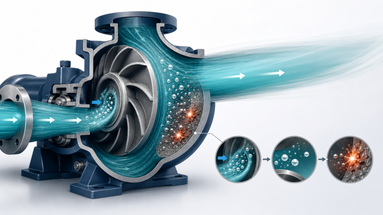
Common hydraulic pump vibration causes include operation far from the preferred region, cavitation, air entrainment, inlet swirl and recirculation.
Ask:
- Did suction pressure or tank level fall?
- Did the liquid temperature rise?
- Is a suction strainer fouled?
- Is there enough intake submergence?
- Was a valve closed or another branch placed in service?
- Does noise change with flow?
Pump cavitation vibration may arrive with crackling noise, unstable suction pressure, reduced head and later impeller erosion. But noise alone is not proof. Air entering through a vortex or suction leak can create similar symptoms.
Plot the actual operating point on the pump curve and review NPSH. Correct the hydraulic condition before balancing an impeller that is being fed disturbed flow.
Check alignment, pipe strain and looseness
Pump misalignment can follow poor installation, base movement, thermal growth or pipe loads. Check alignment under the procedure and temperature condition specified for the unit.
Inspect:
- Hold-down bolts and grout
- Soft foot and base distortion
- Coupling condition
- Pipe supports and nozzle loads
- Evidence of rubbing
- Changes after pipe or seal work
Do not pull connected piping into place with the flange bolts. Pipe strain can distort the casing, shift alignment and shorten seal or bearing life.
Use the spectrum as evidence, not a label maker
A pump vibration analysis normally considers overall level, time waveform and frequency spectrum. Speed-related peaks, harmonics, non-synchronous components and high-frequency activity can help narrow the search.
They are clues rather than automatic verdicts. A strong rotational-frequency component may be consistent with imbalance, but resonance or hydraulic excitation can amplify the same frequency. Multiple harmonics may suggest looseness or nonlinearity, yet the physical inspection must confirm what is moving.
The Hydraulic Institute notes that time-waveform and spectrum data can reveal impacting, cavitation, gear or bearing faults, rubbing and modulation. Interpretation requires the machine layout and operating context.
Investigate bearing evidence carefully
A bearing fault may produce temperature change, noise, lubricant debris or high-frequency vibration before overall displacement becomes dramatic.
Check lubricant type, level, contamination and relubrication history. Too much grease can heat a bearing; too little or contaminated lubricant can damage it. Confirm shaft and housing fits when failures repeat after replacement.
Do not assume the bearing caused the problem merely because it failed. Misalignment, cavitation, pipe strain or electrical current can make the bearing the final damaged component in a longer chain.
A useful test sequence
For a pump that remains safe to operate, a controlled sequence can separate influences:
- Record baseline flow, head, speed and vibration.
- Change flow within the approved range and observe whether vibration follows the operating point.
- Compare duty and standby units under similar conditions.
- Inspect foundation, coupling, piping and visible looseness.
- Review waveform and spectrum at consistent locations.
- Check bearing temperature, lubricant and noise.
- Stop and inspect internally if evidence points to rubbing, severe cavitation or damage.
Do not run through a suspected critical speed or severe vibration merely to complete a test. Site safety limits and the manufacturer’s instructions take priority.
Record enough detail to make the next reading useful
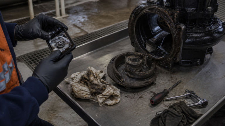
A vibration route should state the sensor position and direction, machine speed and operating condition. Photographs of measurement points prevent gradual changes in placement.
After maintenance, take a new reference set. If a coupling, bearing or impeller was changed, record exactly what was corrected and whether the operating point also changed.
For pump selection or replacement, SHXINHUO’s ISG inline pumps, TD multistage pipeline pumps and sewage pumps have different structures and measurement locations. Use the manual and applicable vibration standard for the exact arrangement.
The diagnostic principle
Do not let one frequency name the failure before the system has been checked. Establish operating condition, compare a trend, form a short list of causes and look for physical confirmation.
That sequence turns vibration data into maintenance evidence instead of an expensive guessing tool.
Technical references
- Hydraulic Institute — Pump Vibration & Troubleshooting Strategies, Part 2
- Hydraulic Institute — ANSI/HI 9.6.4 Overview
- Hydraulic Institute — Pump FAQs
- Hydraulic Institute Data Tool — Pump Principles and Cavitation
Safety note
Vibration testing around rotating equipment must follow guarding, electrical isolation and site procedures. Stop the unit when vibration, temperature, noise or leakage indicates an immediate risk.