Pump Cavitation: Warning Signs, Causes and a Practical Troubleshooting Sequence
Operators often describe a cavitating pump as sounding like gravel is passing through the casing. That noise is a useful warning, but it is not a complete diagnosis. Air entrainment, a damaged bearing, loose pipework and internal rubbing can produce similar symptoms.
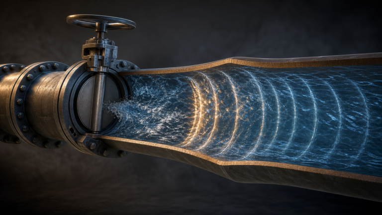
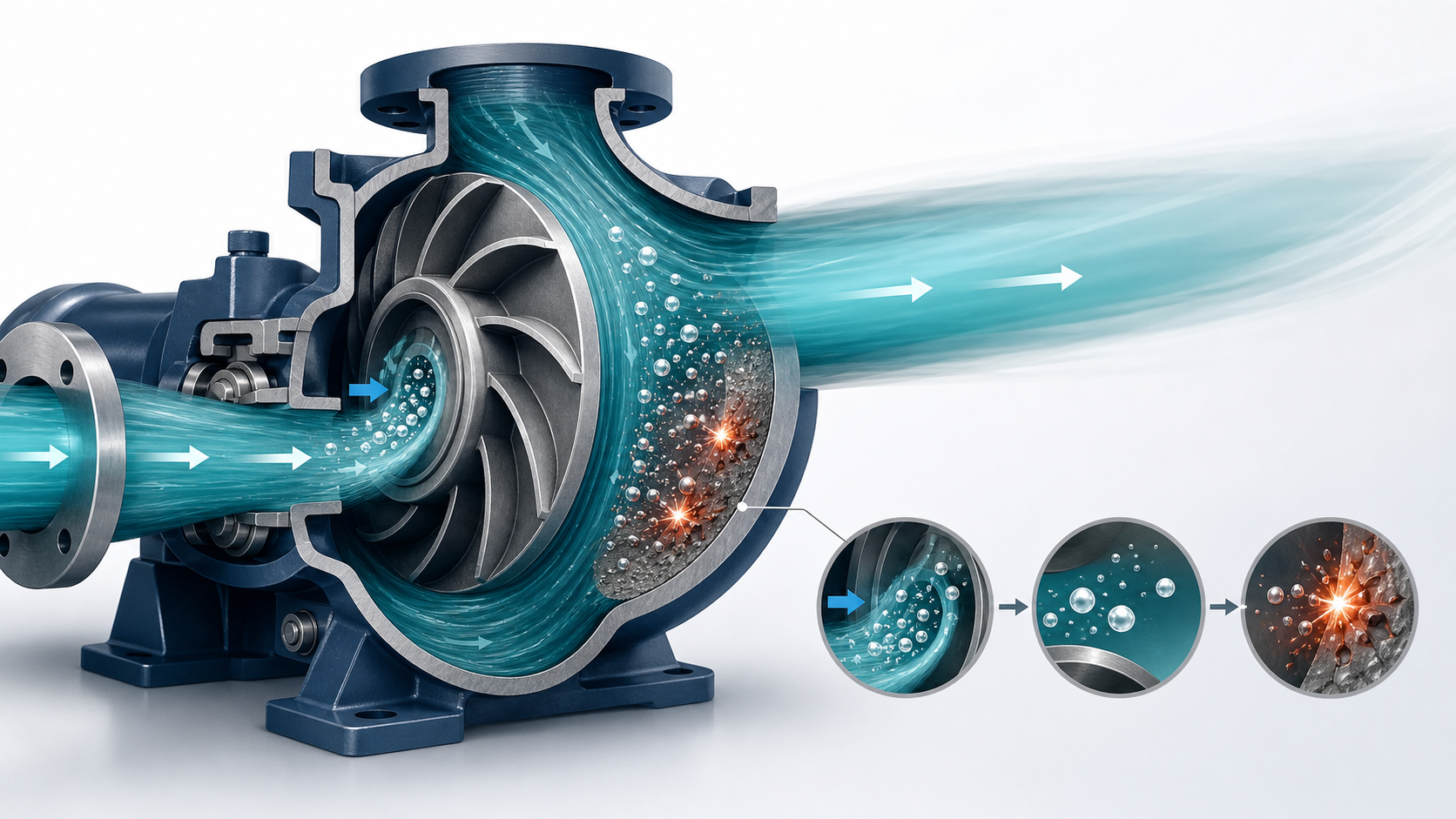
Cavitation is a hydraulic problem. It occurs when local liquid pressure falls below the liquid’s vapour pressure. Vapour bubbles form in the low-pressure region and then collapse as they move into higher pressure. Repeated collapse can erode the impeller and create vibration that damages seals, bearings and connected pipework.
The right response is to investigate the suction conditions and operating point—not simply replace the damaged parts.
Seven signs that deserve attention
1. Crackling or rattling noise
Cavitation commonly produces a sharp crackling sound that becomes a heavy rattle as the condition worsens. Sound alone cannot confirm the cause, but a sudden change should be recorded and investigated.
2. Increased vibration
Bubble collapse and unstable flow can increase vibration. Trend data is more useful than a single reading. Compare vibration amplitude and frequency with the pump’s normal baseline and check whether the change follows flow, tank level or liquid temperature.
3. Loss of head or flow
Vapour occupies space in the impeller passage and disrupts energy transfer. Operators may see a fluctuating discharge gauge, reduced flow or failure to reach the expected duty.
4. Unstable power or motor current
Hydraulic instability can produce changing load. A current trend that moves with flow or suction level can help separate a system problem from a purely electrical one.
5. Seal or bearing failures that keep returning
Cavitation-induced vibration can shorten seal and bearing life. Replacing the seal without checking the operating condition may lead to another failure.
6. Pitting on the impeller
Advanced cavitation can leave a rough, honeycomb-like surface, often near the impeller inlet or vane region. The exact pattern depends on pump geometry and the type of cavitation.
7. Symptoms that worsen at high flow or high temperature
NPSH requirements generally rise with flow. At the same time, hotter liquid has a higher vapour pressure, reducing available margin. A pump that is quiet when cold or throttled but noisy at full flow may have a suction-margin problem.
Understand NPSHA and NPSHR
NPSHA—net positive suction head available—is determined by the system. It accounts for absolute pressure at the liquid surface, static suction head or lift, suction-line losses and the liquid’s vapour pressure.
NPSHR is provided by the pump manufacturer for a specific flow, speed and liquid. Pump curves commonly show NPSH3, the condition associated with a 3% reduction in first-stage head during a standard test.
That distinction matters. Matching NPSHA to the published NPSH3 does not mean cavitation-free operation. Hydraulic Institute guidance recommends an application-dependent margin above NPSHR to protect performance and service life. The required margin also becomes more demanding when the pump operates away from its preferred operating region.
A step-by-step troubleshooting sequence
Step 1: Confirm the operating point
Record suction pressure, discharge pressure, flow, speed, liquid temperature, tank level, valve position and motor current. Compare the calculated total head and flow with the pump curve.
If the pump is operating far to the right of its intended region, flow may be higher and NPSHR greater than expected. If it is far to the left, suction or discharge recirculation can also create noise and vibration that may be confused with classic cavitation.
Step 2: Inspect the suction path
Look for conditions that reduce pressure at the impeller inlet:
- Blocked strainer or foot valve
- Partly closed suction valve
- Undersized or very long suction pipe
- Excessive elbows immediately before the pump
- Air pocket at a high point
- Collapsed flexible hose or damaged pipe lining
- Fouled tank outlet
- Liquid level below the design minimum
Measure pressure as close to the pump suction as practical. A gauge at the tank or a remote header may not reveal the actual loss through the suction line.
Step 3: Check for air ingress
Air leakage is not cavitation, but it can produce similar noise, reduced flow and unstable pressure. On a suction-lift installation, inspect flange gaskets, valve stems, plugs and shaft seals. Because the line may be below atmospheric pressure, air can enter without liquid leaking out.
Also check for vortex formation at the tank and insufficient submergence over the suction inlet.
Step 4: Recalculate at the worst condition
Calculate NPSHA using the lowest liquid level, highest liquid temperature, lowest atmospheric pressure and maximum expected flow. Include dirty-strainer loss if the operating procedure allows the strainer to accumulate debris before cleaning.
Site elevation matters because atmospheric pressure decreases at higher altitude. For volatile or hot liquids, vapour pressure can dominate the calculation.
Step 5: Make a controlled change
If safe for the process, slightly reduce flow by adjusting the discharge valve or speed. If the noise and vibration fall quickly, the result supports a hydraulic operating-point or NPSH diagnosis. Do not throttle the suction valve as a test; that makes NPSHA worse.
Step 6: Inspect the pump
Once isolated and made safe, inspect the impeller, wear rings, inlet passages, seal and bearings. Photograph erosion patterns and compare them over time. Confirm that the installed impeller diameter and speed match the curve being used.
Step 7: Correct the system cause
Depending on the findings, corrective action may include:
- Cleaning or enlarging the suction line
- Reducing unnecessary fittings
- Raising the minimum tank level
- Lowering the pump relative to the liquid source
- Reducing speed or flow
- Selecting a pump with lower NPSHR at the duty
- Reducing liquid temperature where the process allows
- Improving tank inlet and suction geometry
- Moving the duty point closer to the pump’s preferred operating region
Adding a larger motor does not improve NPSHA. Replacing the impeller without correcting the suction condition only resets the damage clock.
Build a useful condition-monitoring record
The U.S. Department of Energy recommends trending vibration because changes over time are more meaningful than a single snapshot. The same principle applies to suction pressure, flow, power and temperature.
For critical pumps, record a baseline after commissioning or overhaul. Review trends at comparable operating conditions. If a pump’s flow slowly falls while power changes, look for wear, clogging or a system change before it reaches a hard failure.
Prevent cavitation at the selection stage
Reliable operation begins before installation. Provide the supplier with the complete suction arrangement, the minimum liquid level, maximum temperature, site elevation and expected operating range. Ask for the NPSHR curve, not just one value at nominal duty.
SHXINHUO’s pump application overview and centrifugal pump product range can help identify an appropriate pump family for HVAC circulation, building water supply or wastewater service. When a distributor or project customer requests selection support, suction layout, liquid temperature and minimum tank level are as important as flow and head. Model selection should then be checked against the actual duty, preferred operating region and NPSH margin rather than relying on nominal pipe size alone.