Pump Mechanical Seal Failure: Read the Damage Before Repair
Replacing a leaking seal can return a pump to service. It does not explain why the seal failed.
A useful pump mechanical seal failure investigation preserves the parts, operating data and installation condition before anything is cleaned or corrected.
Start with the leak history
Record when mechanical seal leakage began:
- At initial start-up
- After a dry or empty-tank event
- Only when hot
- During start and stop
- After piping or bearing work
- Gradually over months
Note the liquid, temperature, suction and discharge pressure, speed, flow and recent alarms. A seal that leaks immediately after installation suggests a different path from one that deteriorates after process temperature changes.
Preserve the evidence
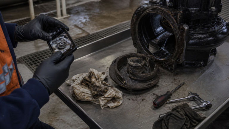
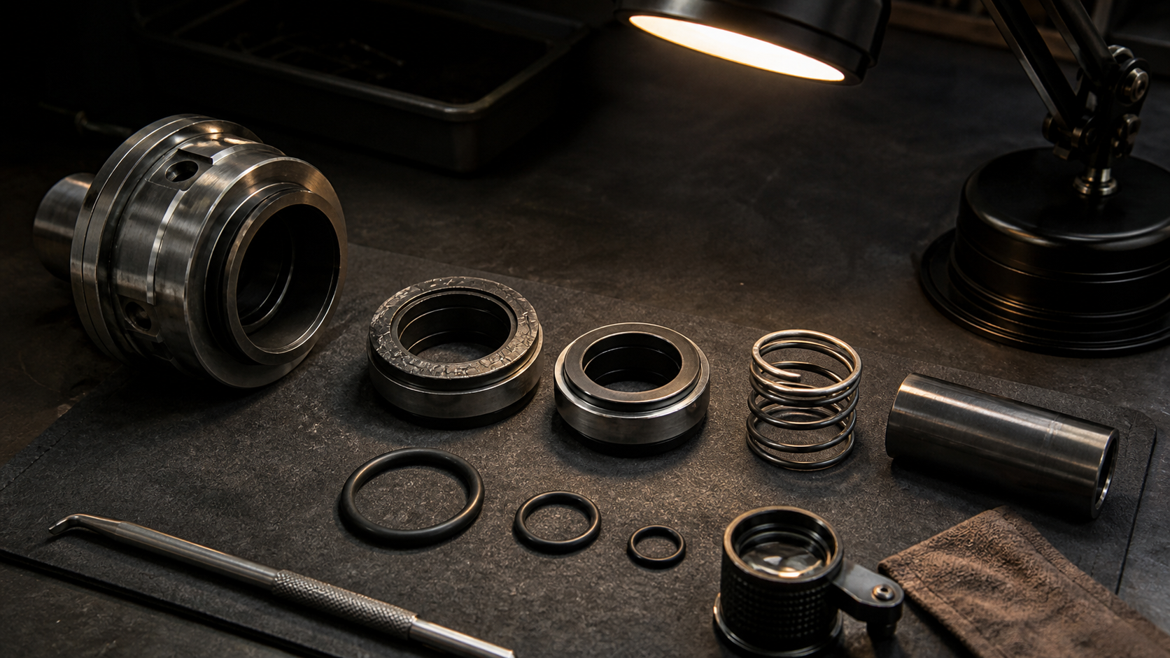
Keep rotating and stationary faces as a matched pair. Photograph the installed position, drive pins, O-rings, springs, gland, shaft sleeve and deposits.
Do not polish faces or scrape away deposits before inspection. Wear tracks, heat checking, chips, blistered elastomers and crystallised product can point toward specific conditions.
The Hydraulic Institute’s current mechanical-seal guide emphasises failure analysis and troubleshooting because the whole pumping system influences seal performance.
Confirm that a lubricating film could exist
Mechanical seal faces operate with a very thin fluid film. Loss of that film creates heat and rapid damage.
A dry running pump seal event can follow an empty suction vessel, failed priming, trapped air, closed valve or loss of seal support. Even a short event can damage faces or elastomers, depending on the design and material.
Check venting, priming, minimum liquid level and start permissives. For a seal chamber, confirm that the selected arrangement can release vapour and keep the faces wetted at the actual pressure and temperature.
Review the seal flush or support system
A blocked, closed or wrongly connected seal flush can remove cooling and carry abrasive or crystallising material into the faces.
Verify:
- Correct source and return points
- Flow direction
- Cleanliness of orifices, strainers and coolers
- Pressure needed to move the support fluid
- Valve positions after maintenance
- Compatibility of the support fluid with the process
Do not increase flush flow blindly. Too much pressure or the wrong source can create leakage, dilute product or overload the seal arrangement.
Check pressure and temperature at the seal chamber
Published pump suction and discharge pressure do not automatically equal seal-chamber pressure. Internal geometry and operating point affect the chamber.
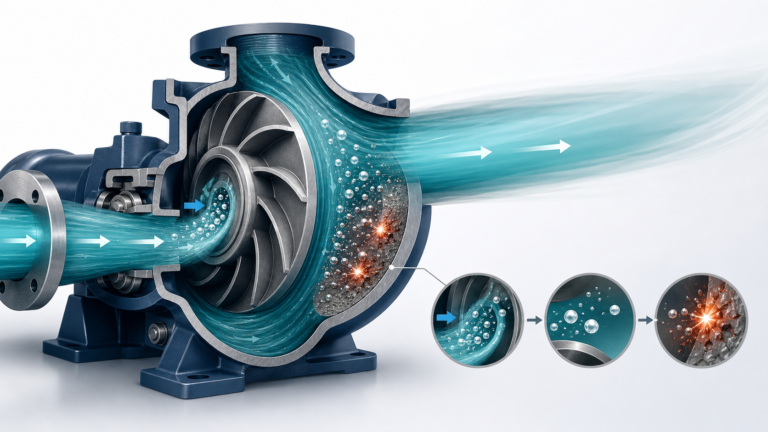
If local pressure approaches the liquid’s vapour pressure, flashing can disturb the face film. Hot shutdown can also raise temperature after flow stops. Record transient as well as normal conditions when failure occurs during start-up or coast-down.
Material selection must suit the liquid, temperature and cleaning chemicals. A carbon grade, elastomer or metal that works in clean water may not tolerate solvent, high chloride or abrasive slurry.
Inspect alignment, runout and pipe loads
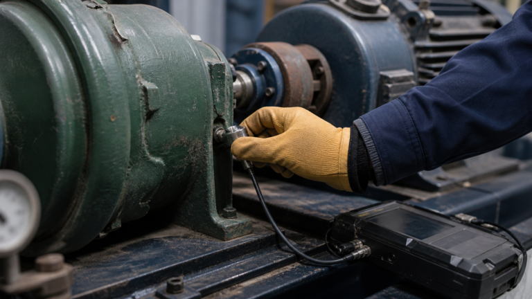
Poor pump alignment, shaft runout, a bent sleeve or bearing wear can make the faces move beyond their intended tracking ability.
Check:
- Shaft and sleeve condition
- Bearing clearances and end play
- Coupling alignment
- Soft foot and base condition
- Pipe strain at the casing
- Concentricity and squareness of mounting surfaces
A new seal installed on a moving or distorted shaft is not a repair. It is a short delay.
Look for hydraulic causes
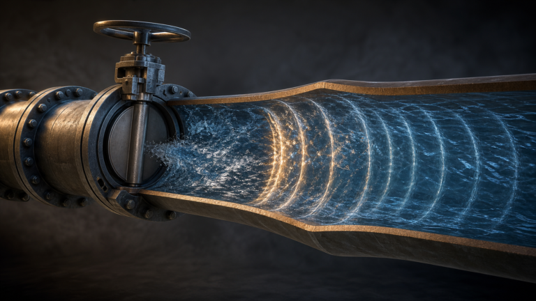
Operation far from the permitted region, cavitation and air entrainment increase vibration and shaft loading. The Hydraulic Institute notes that non-uniform suction flow can lead to noise, vibration, bearing problems and shaft fatigue.
Plot the operating point. Check suction pressure, NPSH, minimum flow and entrained air. If the pump is heavily throttled or repeatedly running empty, correct the operating condition before upgrading the seal material.
Separate installation damage from service damage
Common installation problems include damaged O-rings, dirty faces, incorrect setting length, uneven gland tightening and lubrication incompatible with the elastomer.
Service damage develops after start-up through heat, corrosion, abrasion, vibration or loss of support. The leak timeline and face pattern help separate the two.
Use the exact seal drawing and setting procedure. Mechanical seals that appear similar can require different dimensions, clips or setting plates.
Build a failure report
A compact pump maintenance report should include:
- Pump, seal and material identification
- Service hours and number of starts
- Liquid, solids, temperature and cleaning chemicals
- Pressures, flow, speed and operating point
- Flush or support arrangement and measured condition
- Photographs of every component before cleaning
- Alignment, runout and bearing findings
- Probable cause, contributing causes and corrective action
Avoid writing “normal wear” when the same seal fails repeatedly in a short interval. Repetition is evidence that an operating or installation condition has not been removed.
SHXINHUO’s ISG inline pumps, CDL vertical multistage pumps and MHI horizontal multistage pumps use seal arrangements suited to their specific designs. Confirm materials and procedures against the exact supplied model and duty.
The repair decision
Replace damaged components, but attach the replacement to a cause: restore lubrication, correct alignment, remove pipe strain, repair the flush, change materials or return the pump to an acceptable operating region.
A seal is often an honest witness. Read it before throwing it away.
Technical references
- Hydraulic Institute — Mechanical Seals for the Pump Industry, Second Edition Overview
- Hydraulic Institute — Pump FAQs
- Hydraulic Institute — Eight Tips to Boost Pump Piping Efficiency
- Hydraulic Institute Data Tool — Pump Principles and Cavitation
Safety note
Seal leakage may involve hot, pressurised, flammable, toxic or biologically hazardous liquid. Isolate, depressurise, drain and decontaminate the equipment under site procedures before inspection.