Pumps in Parallel vs Series: What Actually Changes at the Duty Point?
“Install a second pump” sounds like a simple capacity decision. The difficult part is predicting what the system will do after that pump starts.
Two identical pumps in parallel do not usually deliver twice the flow of one pump. Two pumps in series do not guarantee twice the discharge pressure at the operating point. Those statements are true only at particular points on a composite curve. The real duty still forms where that curve meets the resistance of the system.
That distinction affects booster sets, chilled-water plants, transfer stations and wastewater lift stations. It also explains why a station can add a second pump, draw nearly twice the electrical power and gain much less flow than expected.
Parallel pumps add flow at a common head
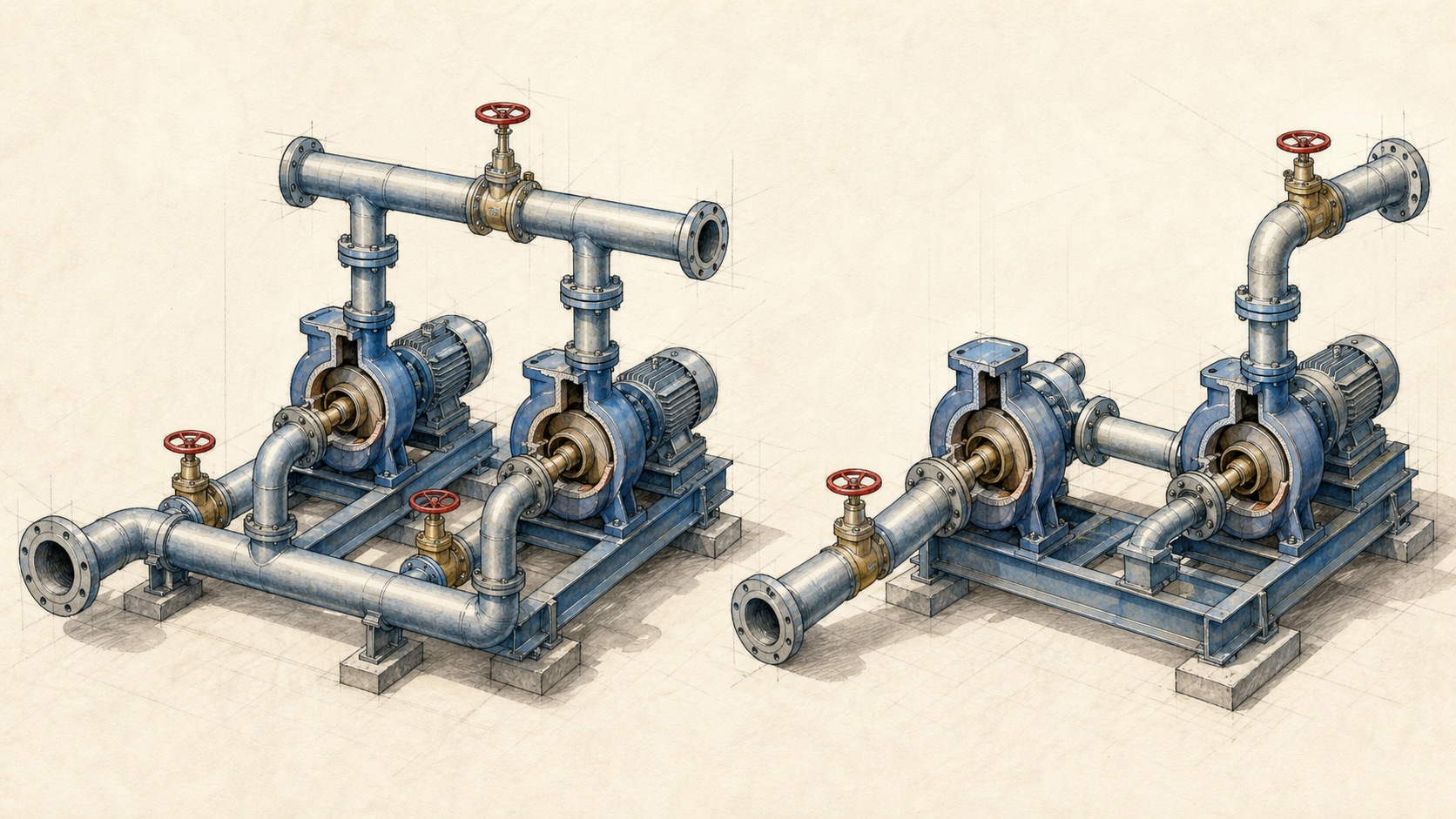
Parallel pumps draw from a common suction source or header and discharge into a common header. To build the composite curve, add the flow of each operating pump at the same head.
If one identical pump delivers 40 m³/h at 40 m head, two identical pumps theoretically deliver 80 m³/h at 40 m head on the composite curve. That does not mean the system operating point will be 80 m³/h. As flow rises, friction loss rises and the system requires more head.
The new operating point is where the two-pump curve meets that higher system resistance.
A worked example: the second pump adds 35%, not 100%
For the illustrative chart, one pump is represented by:
H = 52 − 0.006Q²
The system is represented by:
H = 12 + 0.004Q²
With one pump operating, the curves meet at approximately:
- Flow: 63 m³/h
- Head: 28 m
For two identical pumps in parallel, each pump handles half of the total station flow at a given head. The composite two-pump curve becomes:
H = 52 − 0.0015Q²
This curve meets the same system curve at approximately:
- Total flow: 85 m³/h
- Head: 41 m
The station flow rises by about 35%, not 100%. Each pump is now operating at roughly 42.5 m³/h and 41 m head, a different individual duty from the 63 m³/h and 28 m point of the single running pump.
That individual duty must be checked for efficiency, power, NPSH3 and the manufacturer’s operating region.
Why the system curve limits the gain
The static component of system head does not change much with flow. Friction head does, approximately with the square of flow for a fixed piping arrangement.
A relatively flat system curve allows a larger flow increase when another pump starts. A steep curve absorbs much of the added pump capability as higher head loss. A partly closed valve, undersized header, dirty strainer or restrictive check valve makes the curve steeper and reduces the benefit of parallel operation.
Before adding capacity, verify that the pipework can accept it. The problem may be system resistance rather than the number of pumps.
Series pumps add head at a common flow
In a series arrangement, the discharge of the first pump feeds the suction of the second. To build the composite curve, add the head produced by each pump at the same flow.
If one pump develops 30 m head at 50 m³/h, two identical pumps in series produce about 60 m at 50 m³/h on the composite curve.
Series operation is useful when one pump cannot practically provide the required head, or when a station must cover distinct pressure duties. Multistage centrifugal pumps use the same hydraulic principle inside one casing: each stage adds energy to the liquid.
Series operation requires more than connecting two discharge pipes. The downstream pump casing and seal see the first pump’s discharge pressure at their suction. Confirm maximum allowable suction pressure, casing rating, seal-chamber conditions and interstage instrumentation.
Parallel or series: a practical comparison
| Question | Parallel arrangement | Series arrangement |
|---|---|---|
| What is added on the composite curve? | Flow at the same head | Head at the same flow |
| Typical reason to use it | Variable demand, capacity and redundancy | High differential head or staged pressure |
| Main system influence | Friction limits the extra flow | System head determines the extra flow achieved |
| Key equipment check | Stable staging, minimum flow, header loss | Pressure rating, seal pressure, interstage condition |
| Common misunderstanding | Two pumps will double station flow | Two pumps will double operating pressure |
Duty/standby is not the same as duty/assist
A pair labelled “one duty, one standby” is intended to provide redundancy. Under normal conditions, only one pump runs and the other is available after a fault or on a rotation schedule.
A duty/assist pair is expected to operate together when demand exceeds the capacity or preferred range of one pump. The two-pump operating point therefore has to be part of the original selection.
Confusing the two arrangements creates avoidable problems. A standby pump that is later used as assist may force both units far left or right of BEP. A duty/assist design with no reserve capacity may not meet a project’s redundancy requirement.
Write the operating philosophy in plain language: how many pumps run at minimum, normal and peak demand, and what happens after one pump is unavailable.
Staging variable-speed pumps
Variable speed adds flexibility, but the sequence still needs a hydraulic basis.
Starting a second pump too early can leave two pumps running at low speed and poor efficiency. Starting too late can push one pump beyond its preferred operating region. A good sequence considers:
- System flow or demand signal
- Pump speed and absorbed power
- Differential-pressure setpoint
- Minimum stable flow for each running pump
- Individual pump efficiency at the shared duty
- Minimum run time and limits on starts per hour
- Check-valve behaviour during start and stop
For identical variable-speed pumps, equal speed and balanced flow are a common starting point. The most efficient staging point, however, should be verified with the actual curves and load profile.
Parallel suction and discharge headers deserve their own check
The common suction header must supply the peak combined flow without creating excessive loss or a distorted inlet condition. Poor branch geometry can give one pump better suction conditions than another.
On the discharge side, check-valve selection matters. A valve that closes too slowly can allow reverse flow; one that closes violently can contribute to pressure surge. The header should also provide enough room for isolation, maintenance and instrumentation.
For wastewater stations, plot the system at minimum and maximum wet-well levels. If two pumps operate together, confirm that the resulting rising-main velocity is adequate without creating excessive friction or moving either pump outside its allowable region.
Five questions before approving a multi-pump station
- What are the one-pump and multi-pump operating points?
- Where does each individual pump operate at those station points?
- Does the control sequence match the real demand profile?
- Are suction, discharge and pressure ratings adequate for every combination?
- Is redundancy clearly separated from peak-capacity operation?
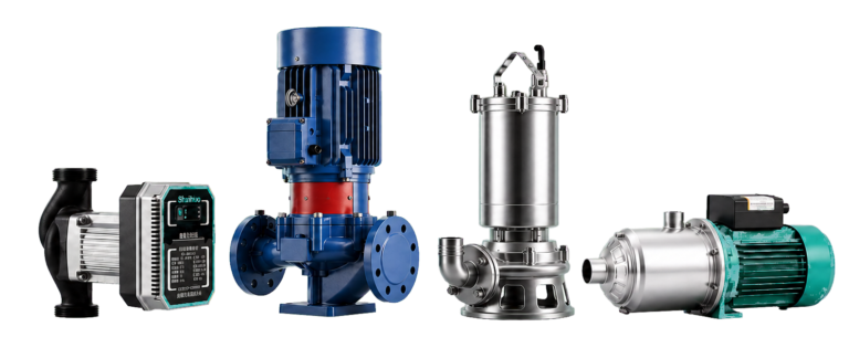
SHXINHUO’s water-supply pump range includes vertical and horizontal multistage options for pressure duties, while HVAC pump ranges cover circulation applications where parallel staging and variable flow may be considered. A useful enquiry should include all required station duties, not only the peak flow.
One pump curve describes one machine. A multi-pump station needs a composite curve, a system curve and an operating sequence. Leave any one of those out and “add another pump” remains a guess.
Technical references
- Hydraulic Institute Data Tool — Parallel and Series Pump Implications
- Hydraulic Institute Data Tool — Combined Pump and System Curves
- U.S. Department of Energy — Pump Systems Resources
Data note
The equations and operating points are an illustrative example, rounded for readability. They do not represent a specific product. Use the exact manufacturer curves and the project system curve for selection.