How to Calculate Total Pump Head: A Worked Metric Example
Many pump enquiries contain flow and building height but omit pressure, pipe loss or the actual system boundaries. That is not enough to select a pump.
The clean way to understand how to calculate total pump head is to compare the energy at the suction boundary with the energy required at the discharge boundary. The pump supplies the difference plus system losses.
Start by drawing two boundaries
Choose a suction point and a discharge point where elevation, pressure and velocity can be defined. For an open-tank transfer system, the liquid surfaces are convenient boundaries. For a booster system, the inlet header and the most demanding outlet may be more useful.
Do not start at the pump flange unless the necessary upstream and downstream conditions are already known. The pump is part of the path, not the definition of the system requirement.
The total-head equation
For a liquid of constant density, a practical form is:
Pump head = elevation difference + pressure-head difference + velocity-head difference + friction and equipment losses
In symbols:
H = (z₂ − z₁) + (p₂ − p₁)/(ρg) + (v₂² − v₁²)/(2g) + hL
where:
- H is required pump head, m
- z is elevation, m
- p is absolute or gauge pressure used consistently, Pa
- ρ is liquid density, kg/m³
- g is gravitational acceleration, approximately 9.81 m/s²
- v is average velocity, m/s
- hL is pipe, fitting, valve and equipment loss, m
This pump head calculation is an energy balance. Head is expressed as metres of the pumped liquid, not simply metres of building height.
A worked water-transfer example
Consider an illustrative clean-water system:
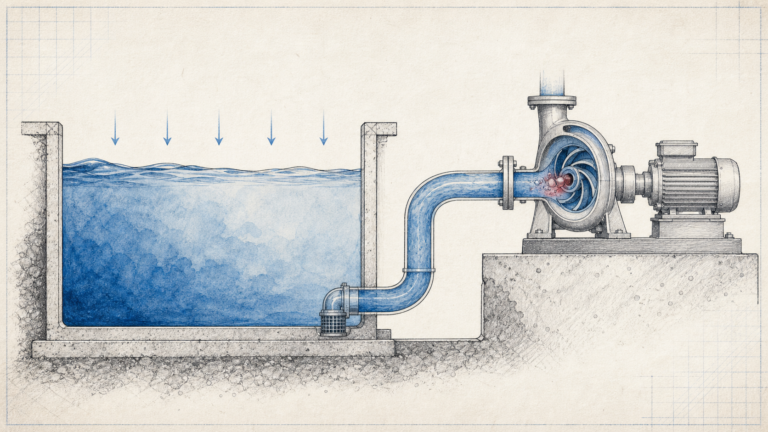
- Suction tank open to atmosphere
- Discharge point 18 m above the suction liquid surface
- Required discharge pressure: 200 kPa gauge
- Calculated pipe and fitting loss at design flow: 7.0 m
- Velocity-head difference between boundaries: 0.8 m
- Water density: 998 kg/m³
The pressure head is:
200,000 ÷ (998 × 9.81) = 20.4 m
The required head is therefore:
H = 18.0 + 20.4 + 0.8 + 7.0 = 46.2 m
If the requested flow is 40 m³/h, the design point is 40 m³/h at 46.2 m—not 40 m³/h at 18 m.
Pressure can either add to or reduce the requirement
If the suction vessel is pressurised, its pressure head reduces the pump requirement. If the discharge vessel is pressurised, that term increases it.
Use gauge pressure at both boundaries or absolute pressure at both. Mixing the two creates an error of roughly one atmosphere.
For liquids other than water, convert pressure to head using the actual density. A pump that produces 46 m of head does not create the same pressure rise in water and a liquid with specific gravity 1.20.
Friction loss is not one fixed number
Pipe friction loss changes strongly with flow. For turbulent water flow in a fixed system, it is often approximated as proportional to flow squared:
hL = KQ²
If the example has 7.0 m loss at 40 m³/h, a first screening estimate at 30 m³/h is:
7.0 × (30/40)² = 3.94 m
That approximation does not replace a pipe calculation. Actual diameter, roughness, liquid viscosity, fittings and valve position determine the loss.
Build a pump system curve
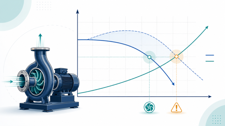
A pump system curve combines the fixed terms and flow-dependent losses. In the example, elevation, boundary pressure and the stated velocity term give a fixed requirement of 39.2 m at design conditions. Friction rises with flow.
Plot several flows rather than one point:
| Flow | Estimated friction loss | Required head |
|---|---|---|
| 20 m³/h | 1.75 m | 40.95 m |
| 30 m³/h | 3.94 m | 43.14 m |
| 40 m³/h | 7.00 m | 46.20 m |
| 50 m³/h | 10.94 m | 50.14 m |
The actual operating point is where this curve intersects the pump curve. If a valve closes, a strainer fouls or another branch opens, the system curve changes.
Static head behaves differently in open and closed systems
In an open transfer system, elevation between free surfaces creates static head. In a completely filled closed circulating loop, elevation gained on the way up is recovered on the way down. Building height affects fill pressure, but it is not normally added as pump head around the closed circuit.
The closed-loop pump overcomes friction and equipment losses at the required flow. This distinction prevents large HVAC pumps from being selected merely because the building is tall.
Check minimum and maximum conditions
One calculation rarely describes the whole job. Repeat the balance for:
- Minimum and maximum tank levels
- Clean and expected fouled pipe condition
- Minimum and maximum flow
- Different numbers of operating branches
- One or more pumps running in parallel
- Normal and emergency discharge pressure
The resulting envelope shows whether the selected pump stays inside its allowable region and whether the motor can cover the full absorbed-power curve.
For clean-water duties, SHXINHUO’s ISG inline centrifugal pumps, TD multistage pipeline pumps and CDL vertical multistage pumps serve different flow and head regions. Send the calculation and system sketch rather than only a nominal pipe size.
A final review checklist
Before issuing the duty point, ask:
- Are the two system boundaries unambiguous?
- Are pressures both gauge or both absolute?
- Has pressure been converted using the actual liquid density?
- Were suction and discharge pipe losses included?
- Were valves, meters, exchangers and strainers included?
- Were minimum and maximum system conditions calculated?
That six-line check catches more errors than adding an unexplained 10% head margin.
Technical references
- U.S. Department of Energy — Improving Pumping System Performance
- Hydraulic Institute Data Tool — Combined Pump and System Curves
- Hydraulic Institute Data Tool — Pipe Frictional Losses
Data note
The worked values are illustrative. Final total dynamic head must use the project’s actual elevations, boundary pressures, liquid properties, internal pipe diameters, fittings, equipment data and operating cases.