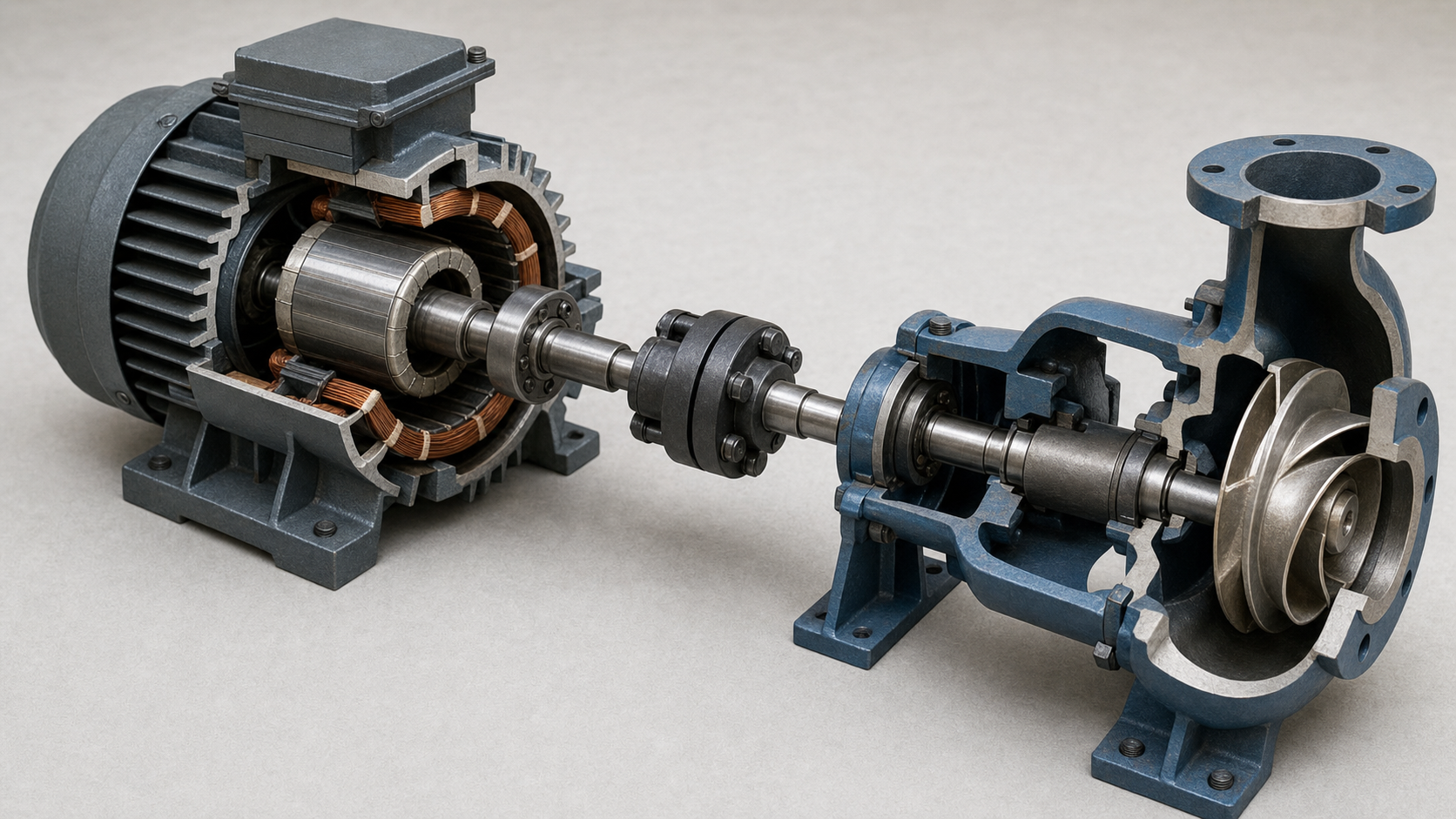
Pump Motor Sizing: Why the Duty-Point Calculation Is Only the First Line
A calculation shows that a pump needs 13.2 kW at the rated duty. The next standard motor size appears to be 15 kW, so the selection looks complete.
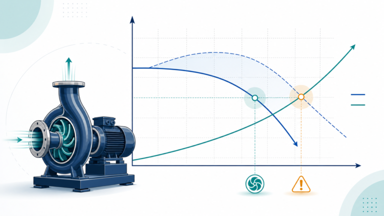
Then a control valve opens, the system resistance falls and the pump moves right on its curve. Shaft power rises to 16.5 kW. The 15 kW motor was correctly chosen for one point and incorrectly chosen for the installation.
Motor sizing is not a single formula. It is a check across the pump’s permitted operating range, using the actual liquid, speed, impeller, ambient conditions and starting method.
Keep three different powers separate
Pump documents often contain several power values:
Hydraulic power is the useful power transferred to the liquid.
Pump shaft power—also called pump input power or absorbed power—is the mechanical power required at the pump shaft.
Electrical input power is the power drawn by the motor and, where fitted, the variable-frequency drive.
The values are related but they are not interchangeable.
For a liquid:
Hydraulic power = ρ × g × Q × H
Pump shaft power = hydraulic power ÷ pump efficiency
Electrical input power = shaft power ÷ motor efficiency ÷ drive efficiency
Use flow in m³/s, head in metres, density in kg/m³ and gravity in m/s² to obtain watts.
A worked duty-point calculation
Consider a clean-water duty of:
- Flow: 90 m³/h, or 0.025 m³/s
- Total head: 42 m
- Water density: 998 kg/m³
- Pump efficiency: 78%
Hydraulic power is:
998 × 9.81 × 0.025 × 42 = 10.28 kW
Pump shaft power is:
10.28 ÷ 0.78 = 13.18 kW
Rounded for a preliminary calculation, the pump requires 13.2 kW at the duty point.
If motor efficiency at that load is 92%, electrical input without a separate drive would be approximately:
13.18 ÷ 0.92 = 14.33 kW
The motor rating is mechanical output, so it is compared with pump shaft power—not with the 14.33 kW electrical input.
The absorbed-power curve decides whether 15 kW is enough
Now consider an illustrative manufacturer-style power curve:
| Flow | Pump shaft power |
|---|---|
| 60 m³/h | 9.2 kW |
| 75 m³/h | 11.0 kW |
| 90 m³/h | 13.2 kW |
| 100 m³/h | 14.7 kW |
| 110 m³/h | 16.5 kW |
A 15 kW motor covers the rated point and appears to cover 100 m³/h. It does not cover the 110 m³/h condition.
Whether the pump can reach 110 m³/h depends on the pump curve, system curve and control arrangement. If that point lies inside the manufacturer’s allowable operating region, the motor selection must address it. If the system physically prevents the pump from reaching it, document the limiting system curve rather than assuming it.
A common alternative would be an 18.5 kW motor, subject to the applicable motor standard, available ratings and project requirements. “Use the next size” remains incomplete until the full load case is known.
Density changes power even when head does not
Pump head is energy per unit weight, so a centrifugal pump curve plotted in metres of head is largely independent of liquid density. Shaft power is not.
If the same hydraulic point is used for a liquid with specific gravity 1.20, the approximate shaft power becomes:
13.18 × 1.20 = 15.82 kW
The 15 kW motor that appeared acceptable for water would already be too small at the rated point.
Viscosity creates a different problem. It can change flow, head, efficiency and power, so a simple density multiplier is not enough for a viscous liquid. Apply the appropriate viscosity correction and obtain a corrected curve.
Speed can overload a motor quickly
Under the affinity-law assumptions, shaft power changes approximately with the cube of speed.
If a VFD increases speed by 5%:
Power ratio = 1.05³ = 1.158
The example 13.2 kW duty could become approximately:
13.2 × 1.158 = 15.3 kW
That is already above a 15 kW rating before considering a different system operating point or efficiency. Do not permit overspeed merely because the VFD can produce a frequency above the motor nameplate base frequency.
At low speed, the risk changes. A self-cooled motor may receive less cooling, while a constant-torque or high-static-head load may still demand significant current. Check the motor and drive manufacturer’s permitted operating envelope.
Service factor is not free design capacity
Some motor standards and markets use a stated service factor; others do not apply it in the same way. A service factor should not be treated as permanent spare power without checking:
- Permitted ambient temperature
- Site altitude
- Voltage and frequency tolerance
- Insulation temperature rise
- Starting frequency
- VFD waveform and cable length
- Enclosure and cooling method
- Bearing and coupling limits
Operating continuously above rated output can shorten insulation and bearing life even when a protective relay does not trip.
Starting duty can matter as much as running power
A wet-well pump that starts six times per hour has a different thermal duty from a transfer pump that starts once per shift. Across-the-line starting, star-delta starting, soft starters and VFDs impose different current and torque conditions.
Check:
- Pump starting torque
- Motor locked-rotor current and torque
- Available supply capacity
- Acceleration time
- Number of starts per hour
- Hot and cold start limits
- Check-valve and system transient behaviour
An oversized motor is not automatically harmless either. It can increase purchase cost, reduce efficiency or power factor at light load and require larger electrical equipment. The target is an adequately sized motor with documented margin—not the largest frame that fits.
A motor-selection checklist for the enquiry
Send the pump supplier:
- Minimum, normal and maximum flow
- System curves for relevant level and valve conditions
- Liquid density, viscosity and temperature range
- Required speed range and control method
- Maximum permitted impeller diameter or trim
- Power supply, starting method and starts per hour
- Ambient temperature and site altitude
- Required efficiency class, enclosure, insulation and certification
Then request the absorbed-power curve across the permitted region and the selected motor rating.
SHXINHUO’s ISG inline pumps, TD multistage pipeline pumps and CDL vertical multistage pumps cover different curve shapes and power ranges. The motor check must use the exact selected hydraulic and supplied motor—not a family-chart estimate.
The reliable selection statement is not “The duty needs 13.2 kW.” It is “The highest corrected absorbed power within every permitted operating case remains below the motor’s usable rated output under the actual site conditions.”
Technical references
- Hydraulic Institute — Pump FAQs
- U.S. Department of Energy — Improving Pumping System Performance
- Hydraulic Institute Data Tool — Pump Curves
Data note
The power curve and 18.5 kW selection are illustrative, not SHXINHUO product data. Final motor sizing must use the exact pump’s absorbed-power curve, corrected liquid properties, applicable motor standard and site derating requirements.